Showing posts with label tip radius. Show all posts

Friday, August 10, 2018

Tin Nanospheres: A Tip Qualification Tool

Using a titanium sample for tip qualification is a standard procedure for certifying tip quality and for estimating the effective probe radius for nanomechanial measurements. This has been discussed in a previous post and while a reliable and quantitative method, it suffers the risk of damaging the probe in process of tip qualification as the titanium sample is quite hard. Another non-quantitative method is to use tin nanospheres on HOPG. Tin is quite soft and by controlling the substrate temperature nucleation can be controlled quite precisely. A sample with approximately 20 nm spheres is ideal for identifying a host of tip problems.  In truth they aren't "spheres" as they are only 8-10 nm tall and 20-ish nm in diameter

In this study several ScanAsyst Air SiN probes that "failed" were used to image this sample sample. PeakForce tapping was used with ScanAsyst, but any imaging mode would work. Because of the symmetric point-like nature of the objects, and because the radius of the Sn spheres (~ 20 nm) is close to the probe radius (~ 2 nm, but < 20 nm).

This allows one to effectively directly image the functional part of the probe. In the first two images one finds objects that look at least half-normal.

In the first image the spheres are all surrounded by something of a halo. The spheres are always in the left margin of this halo. In general, any image with self-similar features can be assumed to reflect imaging artifacts.

The second also reflects self-similar features. The objects all have a similar shape with a tail extending to the top left. What is interesting is that the density of objects is much higher as well. The objects all have multiple companions showing that the functional image surface is split into multiple parts.

While the first two images could be glossed as normal, the third and fourth images show radically damaged probes.

The last image shows a probe so broadened in radius that no objects are visible.


Friday, August 3, 2018

What Happens When A Probe Fails

There are many parameters that determine the performance of an AFM probe. These include the tapping frequency, spring constant, and probe radius. The spring constant is particularly important to control probe normal forces to mitigate shear forces or to provide the required normal force to deform surfaces in a specific range of modulus. Probe stiffness is also important in image quality when imaging soft materials.

The probe radius is the primary design parameter related to resolution. The process of tip qualification to measure the probe radius using a sample with sharp features has been discussed in a previous blog entry. An effective probe radius can be also be measured using controlled deformations while measuring the modulus of a material with known modulus. These methods of measuring probe radius are required for mechanical measurements as well as certifying image quality.

The degradation of the probe radius will impact image resolution as the surface features are convoluted with a larger than anticipated probe radius. A "sharp" probe might have a radius of 3-5 nm, so a blunting to 30-50 nm will result in the dramatic loss of image quality. Probes coated with conducting material, such as platinum or aluminum, will have additional artifacts in such modes as TUNA or conductive AFM in the current channels due to the loss of conducting contact area with the sample.

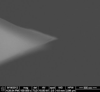
In this post visible apex AFM probes were imaged in a field emission SEM. This probe, the Bruker OTESPA, is called a visible apex probe because the functional part of the probe is at the very end of the cantilever, allowing one of locate objects of interest in the optical microscope of the AFM very easily. The probes were imaged with a 2 kV beam using the through lens detector and field immersion. The larger top image shows a good probe. Even at 2 kV parts of the probe appear to be "transparent" as SE1 secondary electrons are generated near the edges of the probe, while SE2 secondary electrons are generated from the thicker body of the probe.

It is common for probes to fail not only by being blunted or worn-- from their radius being drastically increased-- but from picking up objects. The smaller images show three examples of failed OTESPA probes. The probes showed lower resolution and in all cases either self-similar structures or features with companions. These SEM images show objects attached to the probe. In the second image a blunt object is stuck near the end of the probe, and the shape of this object where it contacts the surface would be convoluted with the sample features. In the third image a sharp object is attached just behind the probe. This can act as an companion probe that contacts features and probes companions or doubles to sample features. The last image shows deposition of material across much of the probe, and the attachment of a significantly large foreign object. An object of this size will not only degrade image quality by make the probe very unstable as it interacts with the surface.

The point of this post is to show that things really do go wrong with a probe when image quality degrades.

Monday, June 20, 2011

Tip Qualification

Tip quality is essential to quality AFM images. In a very general sense, an AFM image is the convolution of the tip morphology with that of the surface being imaged. Ideally an AFM probe has a radius of curvature (ROC) < 10 nm which allows for high resolution imaging of small features. When the ROC is increased due to wearing of the tip or the adhesion of a foreign object to the tip, the imaging resolution is degraded. In some cases, image artifacts may arise. The most common artifacts are self similar features. In some cases all the image structures are triangular in shape due to the fracturing of the AFM tip pyramid or ovoid in shape due to the wearing of the tip or the attachment of a foreign object to the tip. While a radical change in tip performance is readily visible, small changes often go unnoticed and these changes of more difficult to identify on certain types of samples. As such a standard surface morphology is desirable. An ideal standard should be capable of providing quantitative information about the tip quality.

The image above is a titanium surface that has very sharp crystallites emerging from the surface. This is an ideal tip qualification standard as these sharp edges can be used to deconvolute the shape of the AFM tip. By imaging such a sample the sharp edges of the crystal habits can be identified and their shape profile then used to estimate the rip ROC. This process is known as tip qualification, and can be performed just before and after a series of images to certify they are of the highest quality.

This image shows the actual tip qualification. The top left image shows a green "+" at each tip qualification point-- a sharp edge on the titanium crystallites. The bottom left image shows an estimate of the tip shape. The top right image shows the cross section of the tip 10 nm from the tip apex while the bottom right image shows it 20 nm from the tip apex. The diameters of these cross sections are estimated, and user defined upper limits are used to determine if the tip is "good", "suspect" or "bad". This tip is considered "suspect" because the diameter 20 nm from the tip apex is greater than the threshold value of 60 nm.